
capacitors

In addition to the self-builders are also Tuner often faced with the problem of choosing capacitors. Of course, you want to find the optimal component for every purpose, whose properties lead to particularly good results in the corresponding circuit. Unfortunately, the market is almost impenetrably large and myths and half-information are widespread, especially in the audio sector. So here is a little guide.
A capacitor is a device that can store energy in the form of an electric field. Compared to a battery, the energy that can be stored is quite small and, depending on where it is used in the circuit, it may also be released again very quickly, within tiny fractions of a second. Energy storage as such is therefore rarely the purpose of the capacitor, but rather the influence on alternating currents is of interest.
There are no ideal capacitors, they would have no losses and no inductance of the supply lines. However, real capacitors come pretty close to the ideal. Nevertheless, there are different types of capacitors, each differing in how far they deviate from the ideal in this respect and at what price. The good electronics engineer knows about these deviations from the ideal and also which of these deviations are relevant in the present case and which are not. Based on this, you can then choose the cheapest component.
In audio applications, the main uses for capacitors are:
-
-
Screening and filtering of the operating voltage
-
-
-
Coupling audio signals while blocking DC current
-
-
-
As a frequency-determining component in active circuits
-
-
-
As a frequency-determining component in crossovers for Loudspeakers
-
-
-
For frequency compensation of amplifiers
-
-
To suppress interference frequencies
Other applications occur in electronics, but are comparatively rare in audio technology.
A capacitor consists of two (usually) metal contacts facing each other, separated by an insulator. The insulator is called the dielectric and the electric field built up in it stores the energy. It is therefore obvious that the properties of the dielectric are crucial for the capacitor.
The most important capacitor parameter is capacitance. It depends on the area and spacing of the opposing contacts (the plates) and the properties of the dielectric in between. In order to make the capacity as large as possible, one tries three things:
-
-
Make the surface of the plates as large as possible
-
-
-
Make the distance between the plates as small as possible
-
-
Make the dielectric constant of the dielectric as large as possible
Another important parameter is the maximum voltage. If this is exceeded during operation, the dielectric can fail and current can flow through the normally insulating dielectric. Most capacitors will be destroyed by this, but there are some types that can survive under certain circumstances.
Incidentally, the energy stored in the capacitor results from the capacitance and the voltage. Larger specimens can store enough energy to kill a horse, let alone a human. In addition to these two main parameters, there are various other parameters that ultimately have something to do with deviations from the ideal, e.g. B. Leakage currents, ESR, ESL, temperature coefficient, accuracy of the capacitance, dependence of the capacitance on the voltage, dielectric absorption, permissible temperature range in operation, service life, etc.
Here are some common types of capacitor construction:
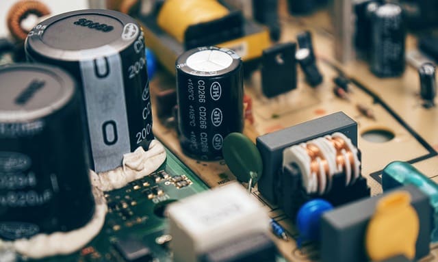
1. Aluminum Electrolytic Capacitors
2. Tantalum Electrolytic Capacitors
3. Ceramic Capacitors
4. Film capacitors
5. Paper or paper-oil condensers
Other types exist but are of less importance.
As you can see, the distinction is based on the dielectric material - no surprise here. What are the properties of these different dielectrics and what does this mean for the application in the audio sector?
|
|
to 1. aluminum electrolytic capacitor: Here is one of the plates of (often roughened) aluminum foil, the dielectric is a very thin layer of aluminum oxide. The other plate consists of a conductive liquid called the electrolyte. The thickness of the aluminum oxide determines the distance between the plates, which is very small here. This results in relatively large capacities with little space requirement and low costs. For capacities in the millifarad range and above, there are practically no economical alternatives to electrolytic capacitors (that's the short term). The disadvantage of the construction is a comparatively high loss resistance due to the electrolyte, the fact that voltages may only be applied with a certain polarity, otherwise the aluminum oxide layer will be "eaten up" by the electrolyte and the relatively short service life, especially at high temperatures, since it the electrolyte can dry out. |
|
|
to 2. tantalum electrolytic capacitor: Here the dielectric is a tantalum oxide and solid electrolytes are used. The result has a higher durability and reliability, but is significantly more expensive and tolerates reversed polarity even less. |
|
|
to 3. ceramic capacitors: In view of the stark differences in the types of ceramics used here as the dielectric, there is little that can be said in common about this type of capacitor. But this much applies to all of them: the thin layer of metal on both sides of the ceramic is usually evaporated or printed on and then the ceramic is "baked". There are also multi-layer variants in which metal and ceramic layers alternate, often stacked on top of each other. The layer thicknesses sometimes go down to the micrometer range. The result is a non-polarized capacitor that tolerates voltage in both polarities equally and is quite reliable. Class 1 is for ceramics that have a narrowly defined temperature characteristic and whose capacitance remains very stable. Examples of such materials are C0G and NP0. These grades are also suitable for applications in filters where film capacitors would otherwise be used. Class 2 is for ceramics whose capacity is still reasonably stable over temperature and voltage, around 20%, but which already have clearly noticeable non-linearities. Example here is X7R Class 3 capacitors have materials whose capacitance can change quite drastically with temperature and applied voltage.
|
|
|
to 4. Film capacitors Here a plastic foil is used as a dielectric. The plates are either applied to the foil as metal vapor deposition or they are separate metal foils that are rolled up together with the plastic foil. Different types of plastic are used, but all film capacitors have good stability of capacitance over temperature and voltage, so they are used at "critical" points in audio circuits. |
|
|
to 5. Paper or paper-oil capacitors The dielectric here is paper, possibly impregnated or soaked with oil. Either metal foil or metal vapor deposition can be used for the plates and the whole thing is wound up again. This variant is somewhat out of fashion because of the problematic reliability. The oil can eventually leak out, or air moisture can get in and change the capacitor properties (for the worse). |


Where is which type used to advantage?
When screening in power supplies, almost only the aluminum electrolytic capacitor comes into question because of the required capacities. If the losses are too high at higher frequencies, other capacitors with a lower capacity can also be connected in parallel. This is generally an underestimated and often overlooked way of achieving the properties of an expensive special component much more cheaply: different types are combined with one another. One parallel circuit of an electrolytic capacitor with a ceramic capacitor has, suitably combined, the capacitance of the electrolytic capacitor and the high-frequency properties of the ceramic capacitor. Using a single capacitor with these properties would be significantly more expensive.
Incidentally, when screening high-frequency interference, class 3 is ideal for ceramics, because the capacity variations are not a problem here and you need a lot of capacity at a low price and small design.
In passive crossovers, too, there is often no avoiding electrolytic capacitors because of the capacity, but non-polar types are needed here, which can also be achieved more cheaply by using two polar types connected in opposite directions. Otherwise film capacitors are in demand here because they have lower tolerances and higher reliability.
Tantalum capacitors are a replacement for electrolytic capacitors in screening, where higher reliability is required with a small design and the higher price is not a problem.
Ceramic capacitors have a reputation for distortion, but that's only true for Class 2 and 3. Class 1 - Materials can be safely used in the audio signal path where film capacitors would otherwise be used for stability, tolerances and low distortion. These include frequency-determining components in filters or amplifier-Compensation. Because of the good HF properties, especially with SMD designs (surface mounting, without connecting wires), they are also used for interference discharge.
Film capacitors are popular for applications in the signal path, i.e. for filters, blocking DC voltage, etc., especially when the required capacities are no longer easily covered by class 1 ceramics, because film capacitors are usually more expensive than ceramic capacitors.
Electrolytic capacitors can also be used to block DC voltage or for coupling purposes, but you have to pay attention to the polarity (a low voltage in the opposite direction of up to about 1V does not matter) and you should clearly oversize the capacitance value (factor 10 if possible) in the interest of low distortion ).
Certain dielectrics have an effect known as dielectric absorption. This means that there is another energy storage mechanism that has something to do with molecular alignments and is not solely due to the electric field. The effect is that shorting the capacitor does not remove all of the stored energy, so when the short circuit opens, a (low) voltage becomes measurable again. The sensitivity of a circuit for this effect is very different, in one case the effect has no practical consequences, in another case it is clearly noticeable. The latter case is rare in the audio sector, but there are applications in measurement technology where this effect can be very disruptive.